| PHOTOGRAPHIC JOURNAL OF BLOWER RESTORATION |
By Philip Underwood
|
Click on photos below to
see enlarged version
 |
(Note: Hold mouse over photo at left to see name of photo as referenced
in text below.)
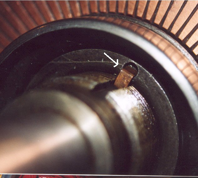
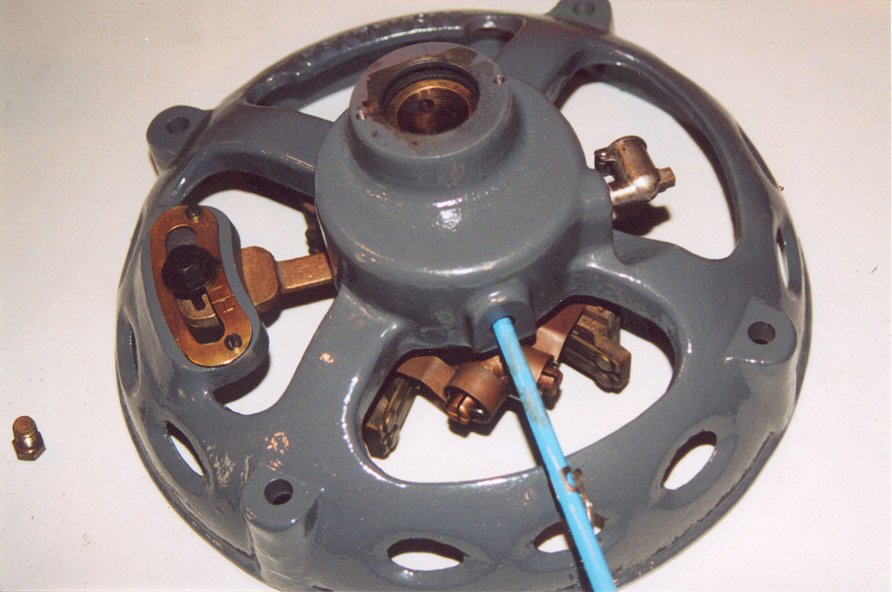
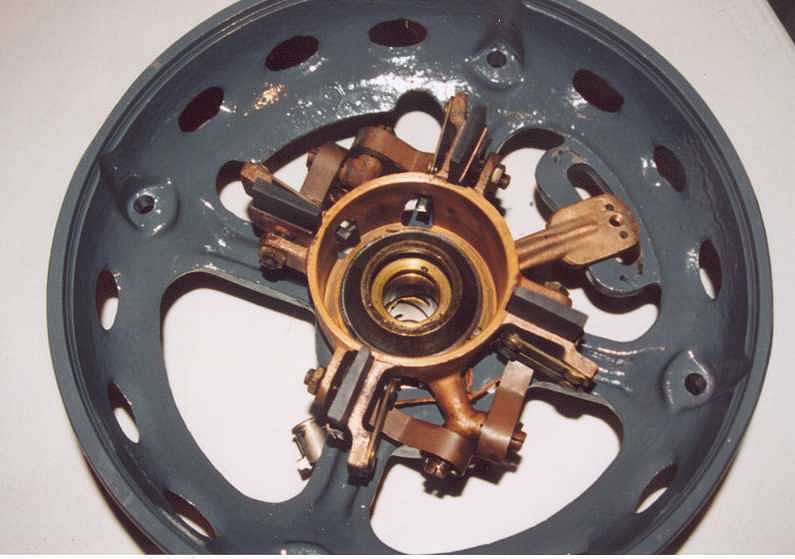
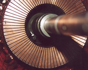
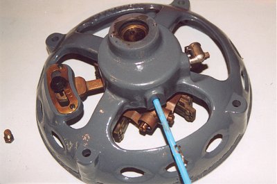
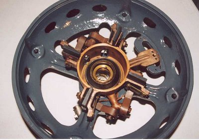
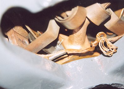
The first pic(armweights.jpg) shows the weights that will disengage the
starting circuit. At rest they are in the position shown. When the motor
comes up to speed they will "fly out" and allow the starting
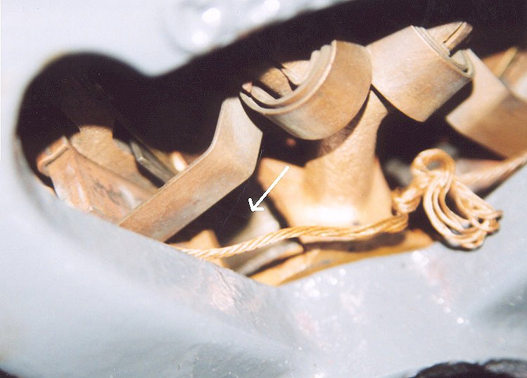
circuit to disengage. They do this by a pin(starterpin.jpg) pointed to
by an arrow. This pin pushes on a plate that is inside the armature(the
left part in picture starterpts.jpg). This will move the shorting bars
(second from left picture starterpts.jpg) that are attached to the spring
barrel (third from left picture starterpts.jpg) to the end of the armature
and short out all of the armature windings.
|
 |
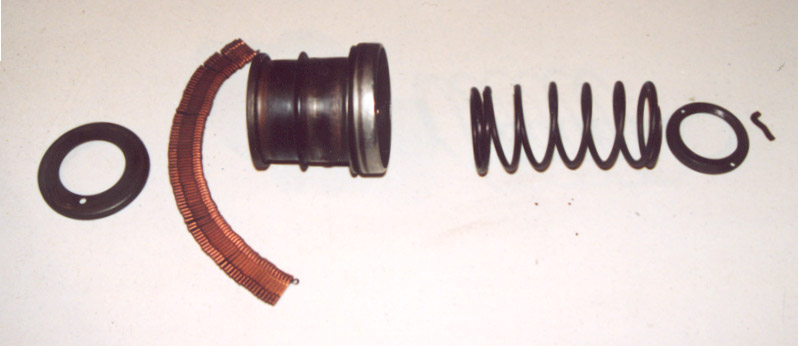
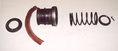
The next three parts are the spring, spring barrel nut, and it's keeper.
The spring and the weights together set the speed at which the motor starting
circuit disengages. If the motor seems to keep engaging the starting circuit
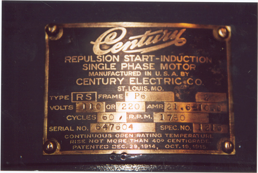
while running and the motor rpm is within 70%-80% of the nameplate speed
(picture motortag.jpg) you might have to "loosen" the nut. If
the motor seems to disengage the starting circuit to soon you will have
to "tighten" the nut. I have never had to do this since I count
how many threads are showing before I remove the nut. If the motor has been
apart before (and most have) you might have to do this. |
 |
Starter parts |
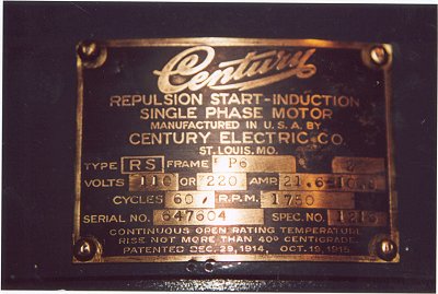 |
Motor Label |
 |
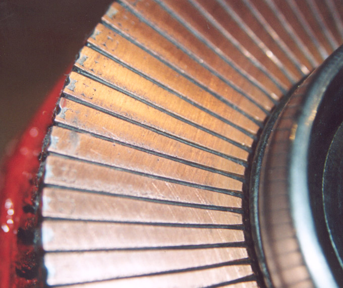
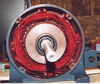
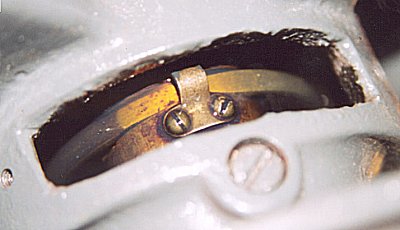
After carefully cleaning the armature of all oil, grease,
and loose varnish you will want to check the commutator. The commutator
should be flat and the dark segments that are between the copper pieces
should be level or just below the copper (picture commseg.jpg). A sharp
narrow piece of steel can be used to remove any residue from between the
copper segments. I use a old piece of utility knife blade to do this. If
the commutator is very rough and uneven it will have to be spun and machined
to flatten it out. A motor repair shop can do this. |
 |
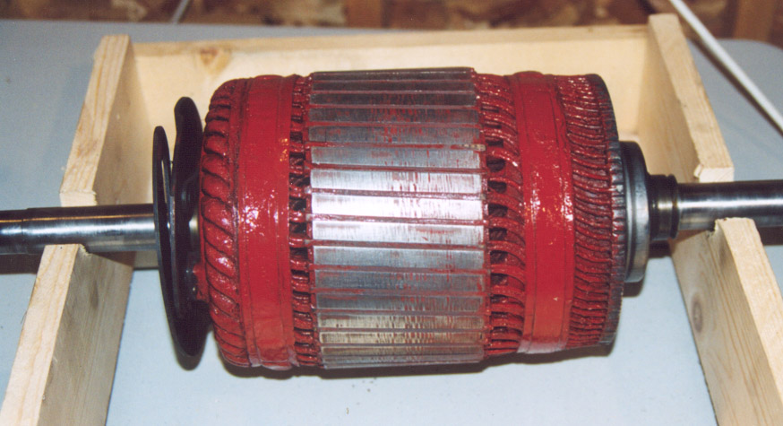
When all of this is done you will want to varnish the armature with a
good grade of motor varnish. This not only helps insulate the windings but
"glues" them in place. Mask off the ends of the armature and generously
paint it. After it is dried, could be a few days, you will want to remove
the varnish from the steel between the windings (picture armcomt.jpg). When
the varnish is dry and the excess is removed the starting parts can be installed. |
 |
The pin plate (picture Starter Parts far left) is slid on
the shaft. Now comes the tricky part. The shorting bars (picture starterpts.jpg
second from left) have to be wrapped around the spring barrel (picture Starter
Parts third from left) and inserted into the armature (picture starterarm.jpg).
The shorting bars have a flat side and a bumpy side. The flat side is down
against the spring barrel. When this is done the spring barrel should slide
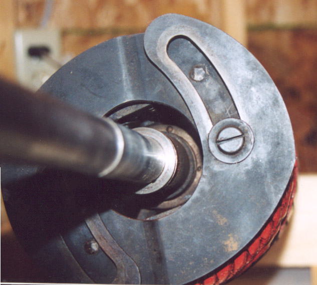
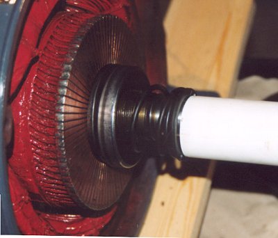
easily into the armature. The spring and the spring nut are slid on the
shaft and tightened (picture starternut.jpg). The white piece in the picture
is a piece of PVC pipe. It is used to help start the nut on the shaft. There
is considerable spring pressure on the nut and it is really easy to cross
thread it. Tighten the nut down until you see the same number of threads
that you had when |
 |
you removed it. Install the armature nut keeper (picture
armnutkpr1.jpg). This is the only thing that keeps the nut from loosening.
After it is installed turn the nut a little to "lock" it in. The
armature is now completely assembled (picture armcomt.jpg). |
 |
|
 |
|
 |
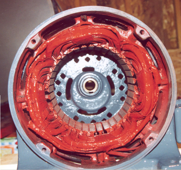
After carefully cleaning the motor shell and windings of loose varnish,
paint, and oil apply a good motor varnish to the windings. Paint the outside
shell with your favorite color of paint and wait for the paint and varnish
to dry (could be a few days). Remove the motor varnish from the steel laminations
that are on the inside. When you are done the shell should look like picture
motorwind.jpg. |
 |
The bearings should be drained of all old oil and cleaned out of all
debris. Flush the bearing cavity with a solvent (I like to use mineral spirits)
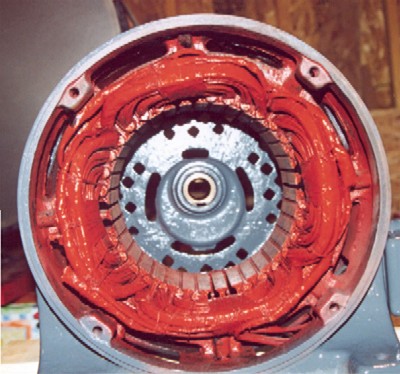
and let dry. When you are ready to insert the armature into the motor shell
use a pencil (picture brushend.jpg) to keep the oil ring out of the way.
I usually install the non-brush end on the motor shell first (picture motorwind.jpg)
since this keeps the armature off the motor windings. Carefully install
the armature into the motor shell until it is stopped by the bearing in
the end cap. Your motor should look like picture motarm.jpg. There is a
small wooden wedge under the armature to help hold it centered in the motor
shell. Check for clearance. There should be a even gap all around. |
 |
At this point I usually check the insulation of the windings with a suitable
insulation checker. A Megger is the traditional way to check the insulation.
The varnish has to be completely dry or you will get a bad reading. There
should be a very high resistance to the shell of the motor (50 megohms or
more). With the armature installed you can check it for any open windings.
You can do this before you varnish but this way you are sure that the motor
is ok after you are done. |
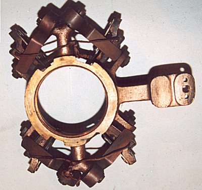 |
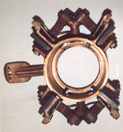
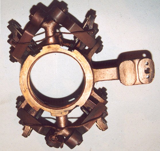
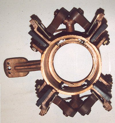
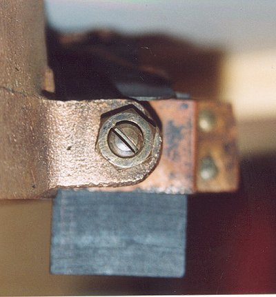
Clean the brush holder of all grease and oil residue. Remove and gently
clean the brushes. They should have nice flat ends without any chips out
of them. You can sand down the brush ends to remove any imperfections. Do
not change the thickness of the brushes. If they are to thin they will not
set correctly in the holder and the motor will not start well. After cleaning,
re-install the brushes into the holder (pictures brushhldr2.jpg and brushhldr1.jpg).
Your motor might have more or less brushes depending on the RPM of the motor
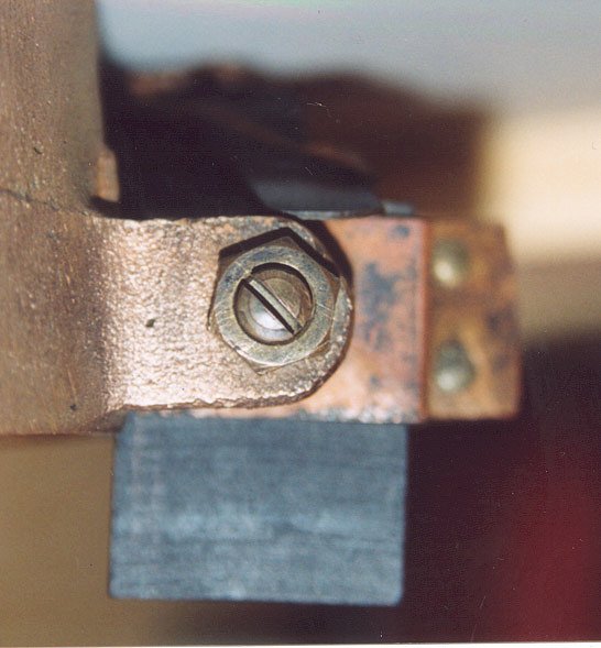
and the local power frequency (60, 25, or 50). Adjust the brush holder nut
(picture brushnut.jpg) until the brush is held from any extra movement.
The brush should be free to move in and out but not side to side. |
 |
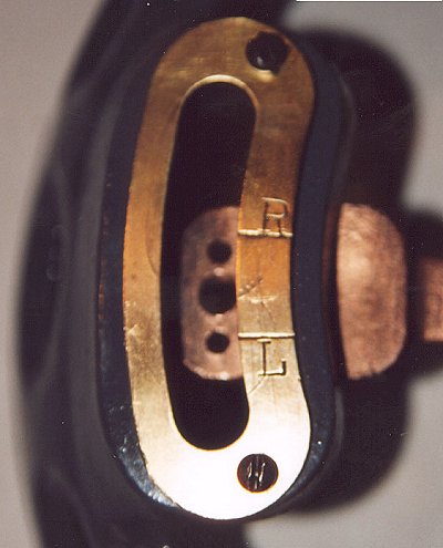
Re-install the brush holder into the brush end of the motor (picture brushhldr3.jpg).
The brush holder screws down until snug. It needs to rotate a little to
set the motor rotation (dirset.jpg). The R is for right rotation as seen
from brush end and the L is for left rotation. Most of the time it will
be set for right rotation. Install the rotation pointer and retaining bolt
(picture brushend.jpg). Remove the small wooden wedge from between the armature
and the motor windings. Using a pencil to keep the oil ring out of the bearing
install the brushend on the motor. Tighten all of the bolts on both ends
of the motor. |
 |
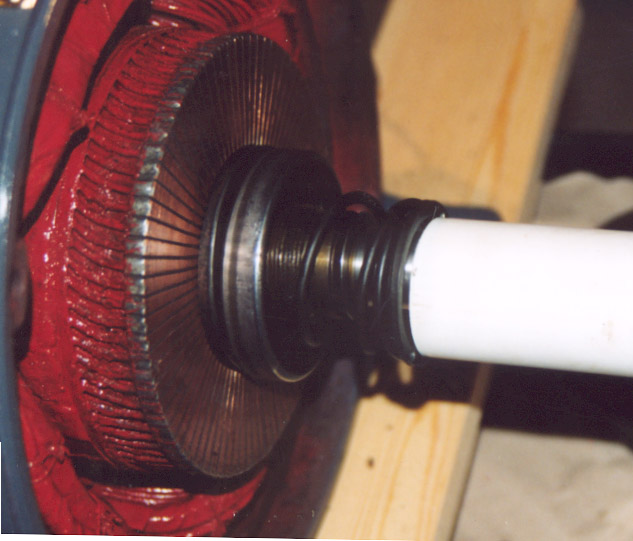
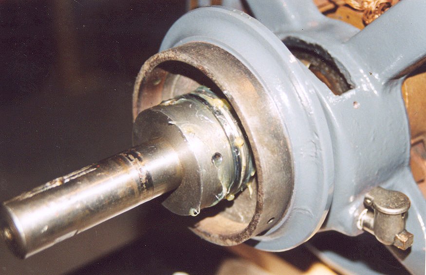
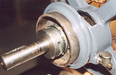
On small Orgoblo blowers and other blowers where the fans
are mounted directly on the motor shaft there will be usually a thrust bearing
attached to the motor. After cleaning all the old grease from the thrust
bearing parts re-grease the thrust bearing and re-install it on the end
of the motor ( I have been using a good grade of automotive front bearing
grease for disk brakes). The thrust bearing is held in place by a tapered
pin. The end of the motor should look like picture thrustbrg.jpg. After
everything is in place add a generous amount of grease and put the cover
on the thrust bearing. Put oil in both of the end bearings until it shows
in the oil cups on the sides of the bearings ( I have been using a good
grade of 30 weight non-detergent oil).
|
 |
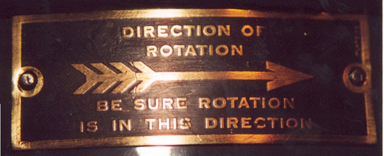
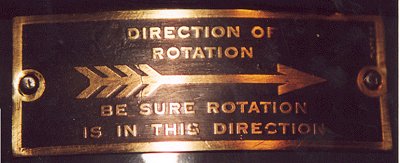
At this point you can try and start the motor. Wire the motor up to it's
starter and turn it on. If everything is ok the motor should come up to
speed and you should hear the starting circuit "kick out" with
a sharp snap. Check the motor rotation and make sure it matches the tag
on the motor( picture motdir.jpg). If it does not loosen the direction nut
and shift the brush holder to the other direction (picture brushend.jpg).
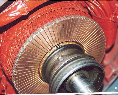
When the motor is turned off the starting circuit should snap back on after
a few seconds. When the motor is off the springs hold the brushes against
the commutator. You should see the shaft through the brush holder(picture
motstop.jpg). When the motor is running and up to speed you will see the
spring barrel ring through the brush holder (picture motrun.jpg). The springs
are pulled back and the brushes are allowed to "float" in their
holders. With the oil adding cups removed from the ends you will be able
to see the oil rings. They should be rotating slowly and be moving oil up
on the bearings (picture oilrun.jpg). |
 |
If everything is working correctly the motor should be making a low humming
sound. The motor shaft should be moving in and out a small amount (1/16"to
1/8"). This means that the armature is in it's magnetic center. If
the motor windings have not moved the shaft should be pumping up against
the thrust bearing. If the motor does not have a thrust bearing the shaft
will just cycle between the two end bearings. There might be a small sound
as the commutator touches the brushes. If the shaft does not move in and
out a little the motor |
 |
should be checked when it is installed on the blower to see if it is getting
excessively warm. These motors should not get hot. After they have been
run several hours ,without the organ being played, they should only be warm
to the touch. If it is getting really hot to the touch, the windings might
have shifted and the armature might not be in the magnetic center. This
will involve a trip to a motor repair shop to make sure all is ok. |
 |
|
 |
|
 |
|
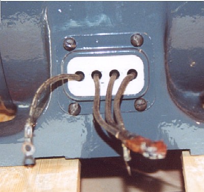 |
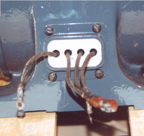
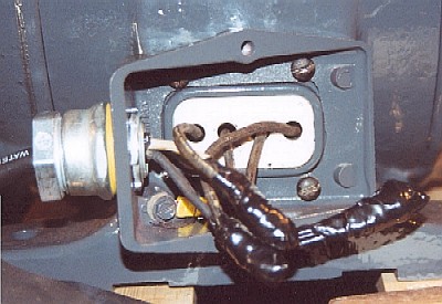
When these motors were made they had a different outlook on electrical
safety. The original motor leads just stuck out of the motor through a porcelain
piece ( picture motwire.jpg). The wires from the starter were just attached
with nuts and bolts and taped up. Now they have a "termination"
box that attaches to the motor. To make the old motors a little closer to
today's safety standards I added a used box from a burned up motor. The
local electric motor shop kindly supplied me with one from a Baldor motor.
I just cut out the back to fit over the existing motor parts and then added
a strain relief for the cable(picture motwire1.jpg).
|
 |
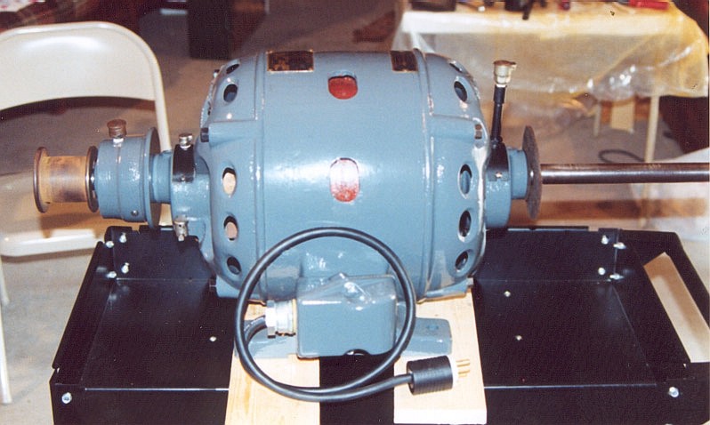
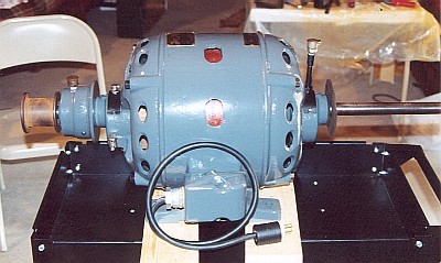
The motor is now ready to be installed in the blower. All
of the little parts have been attached, the oil reservoirs filled, and the
thrust bearing greased. The cable has a plug attached to it which will plug
into a receptacle by the blower (picture motdone.jpg). |
 |
This concludes the motor restoration
section. To continue to the BLOWER RESTORATION page, click here. |