| MUSEUM OF YESTERDAY |


A FEW WORDS OF CAUTION FROM THE OLD PROFESSOR |
|
 |
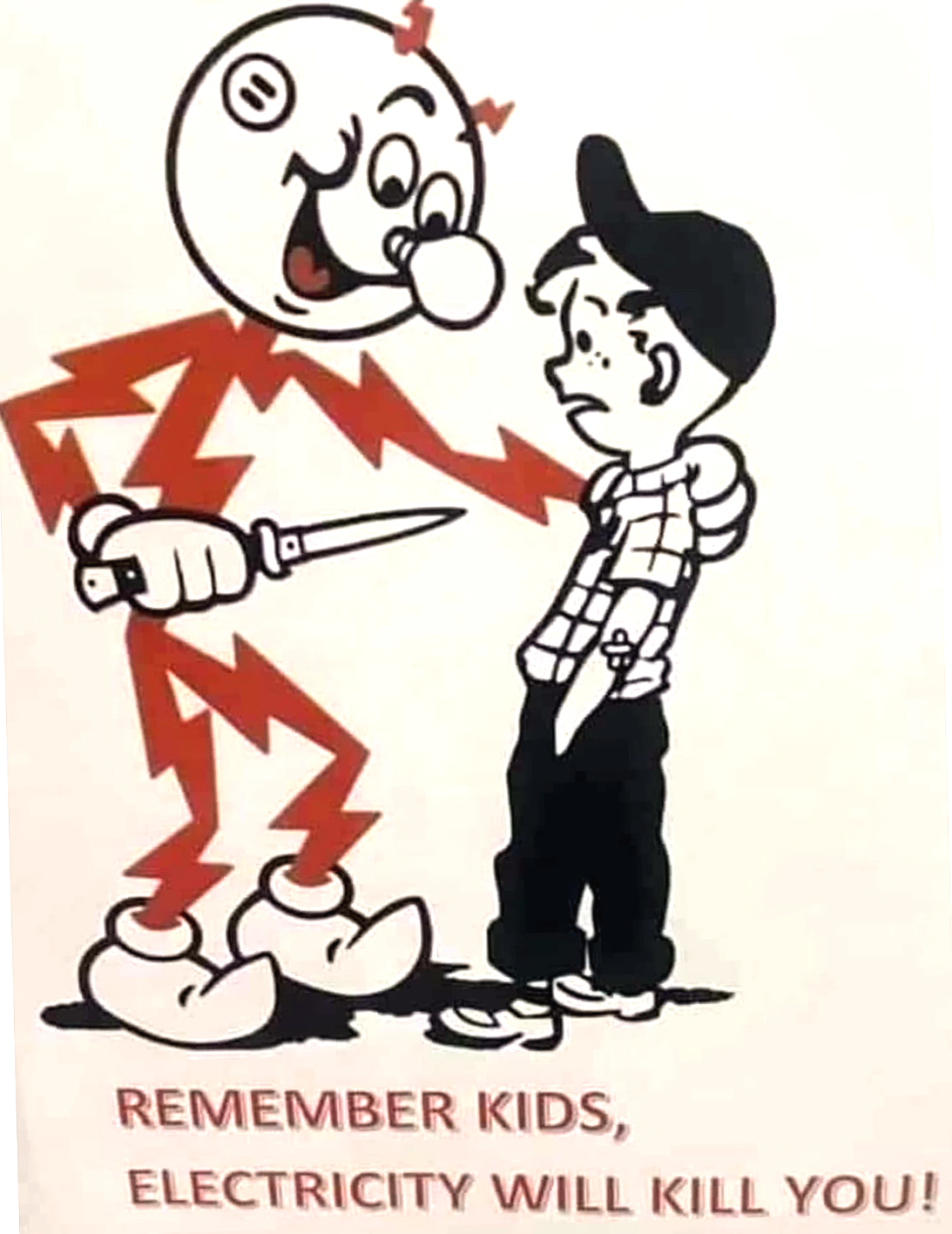
If you are visiting this site, it is possible that you are contemplating, or are in the process of restoring an antique radio. If that is the case, I would like to offer a few suggestions to keep you safe and to protect your investment in your vintage set. If you prefer to just continue your tour of the museum's radio collection, you may do so by clicking the icon below, or on the "next gallery" link at the bottom of the page. Remember that old radios can be dangerous or even lethal if they are mishandled, or if the technician is not familiar with the different requirements of these older sets. |
DANGER-HIGH VOLTAGE:
1. Tube circuits generally operate at dangerous voltage levels. Plate (B+) voltages in old radios can often exceed 300 volts, so always work safely and observe general safety rules for working on potentially lethal electrical current.
BEWARE-HOT CHASSIS:
2. Many sets manufactured during the "Vintage Radio Era" did not contain power transformers. These sets were called "hot chassis" sets because one side of the 120 volt AC line cord was connected directly to the metal chassis. These radios generally had non-polarized power plugs, so turning the plug 180 degrees when inserting it in the AC wall outlet, could easily make the chassis a "hot wire" to the building electrical system thereby providing a dangerous or lethal shock hazard.
When working on these sets, it is advisable to use an isolation transformer to isolate the set from direct contact with the power lines. If that is not possible, exercise extreme caution when touching any components, and if possible, use a volt meter to determine that the chassis is at "neutral" potential in reference to the house or building power.
When replacing a power cord on a "hot chassis" radio, it is advisable to install a polarized plug, that is one with the neutral prong larger than the hot prong so that it can not be plugged into a standard outlet with the hot wire connected to the chassis. Make sure also that the proper polarity connection of the line cord is verified with a meter or other suitable test instrument.
CAPACITOR CAUTION:
3. Vintage radios contain capacitors which are made from paper, cardboard and metal foil. They often contain chemicals called "electrolyte" which are similar to storage batteries. Over time, these devices can dry out, and they may become "shorted" or open to the flow of electricity. Applying power to a radio which has not been powered for a lengthy period, can often cause these capacitors to reveal their condition by burning, exploding, or shorting the power processing tubes and circuits of the radio. This usually results in expensive damage possibly to rectifier tubes, speaker field coils, transformers, and other parts which may not be easily replaceable.
We recommend that you NEVER apply full line voltage to a questionable radio. As a precaution, voltage may be gradually supplied through a "VARIAC" or variable voltage transformer. Applying low voltage and gradually increasing it over a period of several minutes or hours, will usually show up faults while still minimizing damage to the set.
As a precaution, however, any set with original capacitors in the power supply chain, should always be "re-capped," that is replace all capacitors in the high voltage path through the entire radio, before attempting to apply power.
4. BEWARE OF ROTTEN WIRING:
If your set has an older line cord, or if wiring inside the set is cracked and the insulation is damaged, assume that these wires must be replaced before applying power to the set. Shorted line cords can present direct shorts to the household power lines, causing fires, and welding machine style arcing that can cause severe burns. Always inspect carefully for visual evidence of failing wire and insulation before attempting to apply power.
5. FILAMENT SUPPLY PERILS:
Unlike modern day solid-state devices, vacuum tube radios require a source of heat, within the tubes themselves, to initiate the flow of electrons. This is accomplished with a tungsten or carbon filament much as you would find in an incandescent light bulb. Through the period of 1920 to the 1960s, that point when vacuum tubes gave way to transistors in most radios, tubes employed a wide variety of filament voltages. It is therefore a critical step to identify the tubes through the use of a tube manual or tube specification sheet, before making any attempt to replace or substitute tubes in any radio.
The earliest tube sets of the Deforest and Marconi era, employed storage batteries for their power sources. Filament voltages ranged anywhere from 1 volt DC to as much as 5 or 6 volts. These early tubes, like their Edison light bulb counterparts, usually employed carbon filaments. Carbon filament lamps and tubes are specifically intended for use on BATTERY DC VOLTAGES. Applying any voltage derived from an Alternating Current source increases the chance that the tube will fail. If DC power supplies other than batteries are employed, they must be specifically designed for this purpose, and the DC output must be highly regulated and filtered. Tubes commonly found in these battery era radios were identified by numbers such as 01-A, Type 10, 27 and such similar designations. Note that this same rule applies to later "portable" sets such as the popular Zenith "Transoceanic" portable which also used 1 volt DC tube filaments of a slightly more modern design.
AC POWERED SETS:
AC powered tube filaments were furnished in a wide range of voltages. Most tubes that were designed for power transformer operated sets, utilized five and six volt filaments, and were intended to be wired in parallel and supplied by a dedicated filament winding on the set's power transformer. Some early AC era sets did use filament voltages as low as 2.5 volts. Sets of that era often contained two and three digit tube numbers such as Types 45, 80, 27 and 2A3, among others.
Sets which were designed for transformer-less operation, such as the hot chassis sets described above, usually had the filaments connected in series, and they often employed higher filament voltage tubes. It is extremely important for the technician to understand the significance of these tube type numbers as they relate to the voltages applied to the filaments.
Each type of vacuum tube is assigned an identification number. In receiver tubes, this identifier is often made up of both letters and numbers. While there are a wide range of exceptions, the first number(s) in the identification string usually indicate the filament voltage of the tube. For example, a tube with the type number 6J5 or 6SN7 would be assumed to have a filament voltage rating of 6.3 volts. Tubes with higher numbers, such as 35Z5, 50L6 or 117L7, would have filament ratings equal to the number prefix of the identifier. The 35Z5 would operate on 35 volts, the 50L6 on 50 volts, and so on.
Many "economy" hot chassis radios of that era used what is called the "famous five" tube lineup. This consisted of a 35Z5 or 35W4 rectifier, a 50L6 or 50C5 audio output tube, a 12SQ7 or 12 AV6 first audio/detector tube, a 12SK7 or 12 AU6 IF amplifier and a 12SA7 or 12BE6 converter-oscillator. Adding up these filament voltages (35 + 50 + 12 + 12+ 12 ) totals 121 volts, so when wired in series, this string of tubes could be connected directly across a 120 volt power source (as in normal house current), without the need for a transformer or voltage dropping ballast resistor. The tube numbered 117L7 was specially designed for use in one-tube appliances such as record players and code oscillators. That tube also could be directly connected across an AC power line without the need for any voltage compensating devices.
When any devices, such as light bulbs or tubes, are connected in "series," remember that the circuit is broken if the filament in any one tube or device fails. If the radio has power applied but the tubes do not light, it is possible that one tube filament has failed, and this is keeping the other tubes from receiving the voltage they need to operate. It is therefore advisable to utilize a tube tester instrument, if one is available, to verify the condition of all tubes prior to beginning any under-chassis troubleshooting.
A NOTE OF CAUTION HERE:
There were a number of sets manufactured in the 1930s that utilized dropping resistors or ballasts to absorb excess filament voltage. One example is the popular Zenith 6D-312 which employed a 50 volt dummy tube called a "ballast." These sets had a tube lineup consisting of a 25 volt rectifier, a 25 volt output tube, and three six-volt tubes for the first audio, IF and converter stages. Since the filaments themselves only consumed 68 volts when connected in series, it was necessary to provide a dummy tube or resistor to absorb the remaining 50 volts of the 120 volt AC line voltage.
Some other sets in this same era, employed asbestos insulated line cords which had built-in resistors to absorb excess filament voltage. These cords contained two unimpeded wires that supplied the B+ power or rectifier. The filaments, however, were fed through the third wire which was a high-resistance conductor. The cords generated some heat when operating, and it was important that the asbestos insulation be in place to prevent overheating and fire.
Should you encounter a radio that contains either a ballast tube or a ballast line cord, it is advised that you do not replace the ballast with anything except a UL rated proven method of substitution. There are tricks-of-the-trade for dealing with these devices, but employing them in the field requires a good knowledge of the engineering factors involved. Asbestos cords, which have become frayed, also present the risk of asbestos contamination which can result in a form of lung cancer. If the cords are disturbed in any way, they must be dealt with as hazardous material and disposed of according to law.
Repair or replacement of asbestos line cord resistors is therefore best left to someone who has the electrical knowledge to come up with a safe replacement for the ballast component, and also the training to handle any hazardous materials in the cord or set itself.
Failing coupling capacitors between the audio stages in a radio can cause damage to the audio output tube. The coupling capacitor's function is to block the high voltage DC applied to the plate of the first audio stage, while letting the AC audio component through to the grid of the output tube. If the coupling capacitor fails, it can dump partial or even full DC plate voltage onto the output tube grid, thereby biasing it into full conductivity. When this happens, the tube overheats and becomes cherry red, which destroys it. It is therefore very important to thoroughly examine this capacitor and replace it if there is any potential of it failing.
CARE AND FEEDING OF ELECTRO-DYNAMIC SPEAKERS:
Permanent magnet speakers did not enter into wide use until the end of World War II. Radios made before the War usually employed electro-dynamic speakers. These speakers had an electro-magnet instead of a permanent magnet as modern speakers do. The magnet coil served a dual function. It provided magnetism to repel the voice coil, and it also served as a filter choke to remove AC hum from the power supply.
Since the field coils were connected directly to the high voltage B+ circuit, the coil carried dangerous voltages. In the event of an internal short to frame, the speaker itself could become energized with high voltage, and touching between the speaker and the metal chassis could administer a severe or lethal dose of electricity. It is therefore recommended that a voltmeter be used to check the speaker for leakage.
There was another unique feature involved in these speakers. It was called "Hum Bucking." In order to cancel out any remaining AC hum that might escape the filtering circuit of the radio, a separate coil was installed in opposing parallel to the voice coil. A small amount of the DC voltage from the speaker field coil was applied to this "hum bucking" coil winding. Since any hum appearing in the audio would be 180 degrees out-of-phase with the opposing winding of the hum bucking coil, the AC components in both coils would cancel each other, thereby providing an audio signal free of AC hum. Remember when servicing these speakers to insure that the hum bucking circuitry is maintained and properly connected to insure the required opposing phases effect.

Finally, here is a list of suppliers and resources that we have compiled, that may be of use to restorers of vintage electronics equipment:
Bob's Antique Radios and Electronics
(Source for capacitors, resistors, and specialty polot lamps)
www.radioantiques.com
111 East 29th Street
LaGrange Park, IL 60526 (USA)
E-Mail: :RadioBob1@sbcglobal.net
_____________
(Source for restoration parts including tubes, transformers, rf coils and capacitors)
www.tubesandmore.com
6221 S Maple Ave, Tempe, AZ 85283 (480) 820-5411
_____________
TP TOOLS.COM
(Supplier of VHT wrinkle paints and metal repair supplies)
7075 Ohio 446, Canfield, OH 44406
_____________
RADIO DAZE
(Reproduction knobs, decals, glass and plastic dial components, custom graphics and parts)
Sales Line (877-OLDTUBE or 653-8823) or 585-624-1099
____________
TOWN AND COUNTRY HOBBIES
(Specializing in LED miniature bulb etrofits for model railroad and radios)
PO Box 584
Bernville, PA 19506
info@towncountryhobbies.com or by phone at 973-942-5176.
____________
BULB TOWN
www.bulbtown.com
Source for 6.3 and 12.6 volt E-10 and Ba9S base LED pilot lamp replacements.
_____________
Ryder's manuals in PDF form
http://www.nucow.com/allriders.htm
______________


