This is a special
visual documentary detailing the construction of direct electric action
pipe chests, produced in my home workshop. The tutorial details the construction
of a 61-note chest designed to hold the metal tibia rank, however, all
chests on the organ follow the same basic design. The chests are constructed
of 1 X 8 and 2 X 8 Poplar lumber, because I have determined through experience
that Poplar has ideal grain and cellular construction to prevent wind-leaks
through the cellular matrix of the lumber itself. Peterson electric valves
were chosen for use throughout the project because I also determined,
through experimentation, that Peterson's valves are more reliable as far
as opening and closing against pressure, than were the other brands of
valves I tested. These single-rank unit chests can be used in a chamber
where appearance is not important, or they can be finished as furniture
and installed exposed in a room where they will be seen,.
Click images to see
enlarged photos
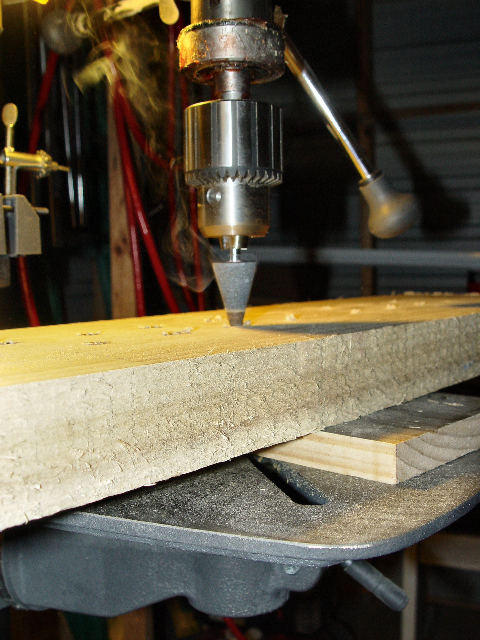

First step in the process is to prepare the
toe board. Pipe placement is drawn up from an actual placement fitting
of pipes to the area of the toeboard. Next, holes are drilled under the
location of each pipe. A heated stone is used to bore the "V"
shaped pipe toe holes
The wind box is constructed next. 1x6 Poplar
is used for construction. Toe board is then fitted to chest body. A plane
is used to clear any irregularities from the surfaces, and then the board
is cut on the sides and ends to fit the wind box. One of the common mistakes
made in chest construction is failure to insure a smooth and well sealed
underside to the toe board. If there are irregularities in the toe board
under-surface, the valves will not seat correctly and ciphers will result.
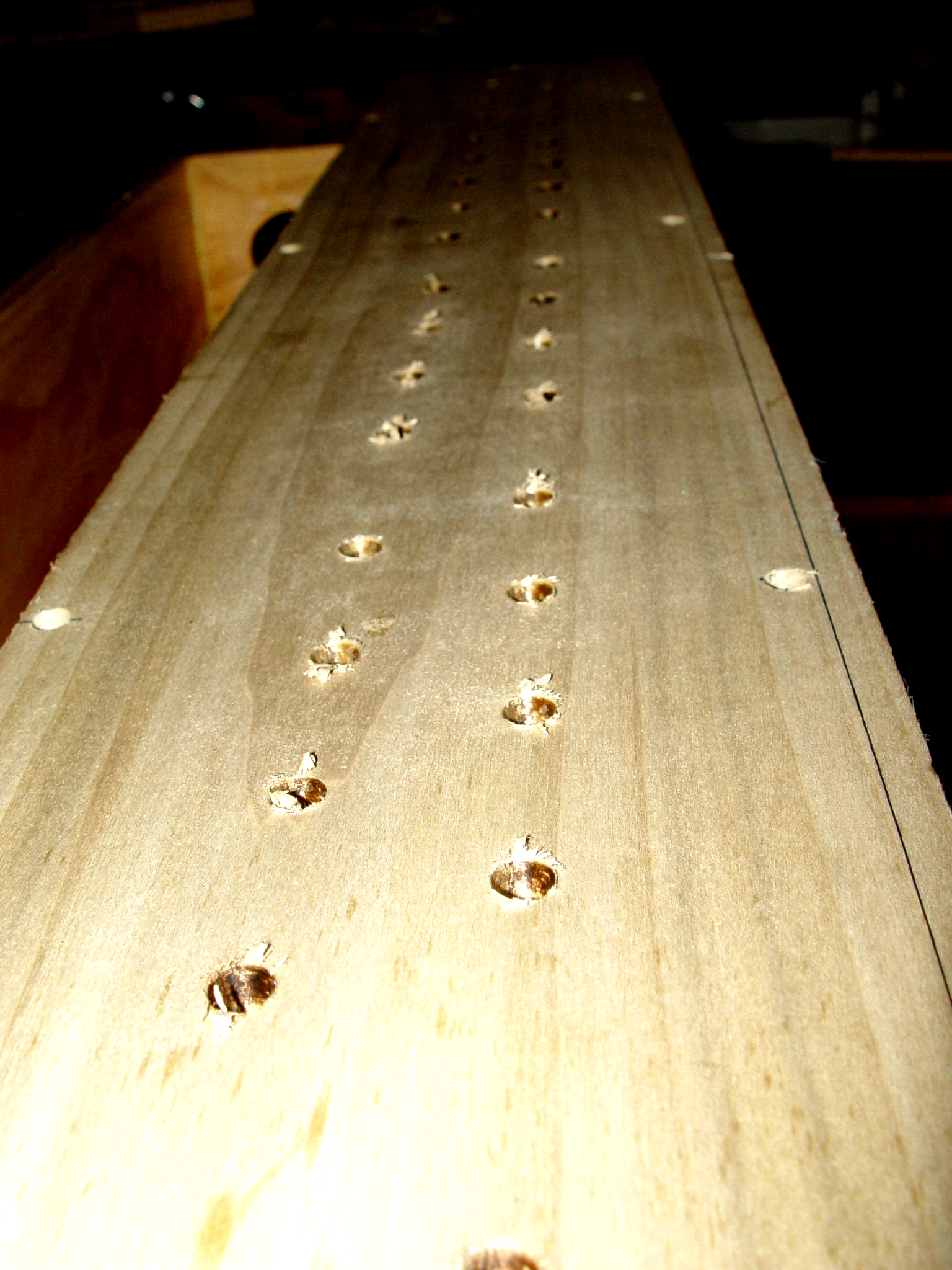
Once the toe board is cut and sanded to fit
the wind box, holes in toe board are used as a guide to drill and insert
the special threaded brass inserts into the chest.
Drilled toe board reflecting pipe placement.
This sixty-one note rank is built side-by-side on a dual section chest.
This is done to produce a more aesthetically appealing layout in the event
that the chest is used for exposed pipe work.
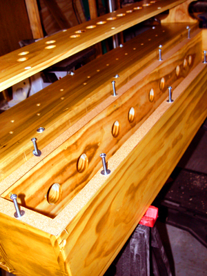
Two-section chest showing inside construction
and air passages in wind box.
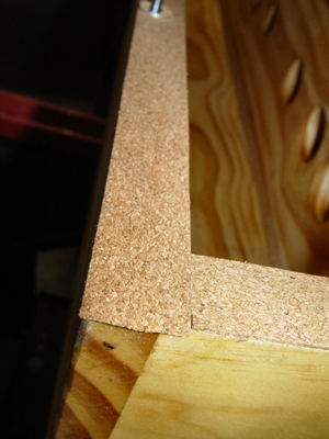
Detail of gasket installation. A cork gasket
is used on both the toe board and bottom board mounting surfaces.
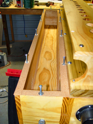
Another view of chest interior construction
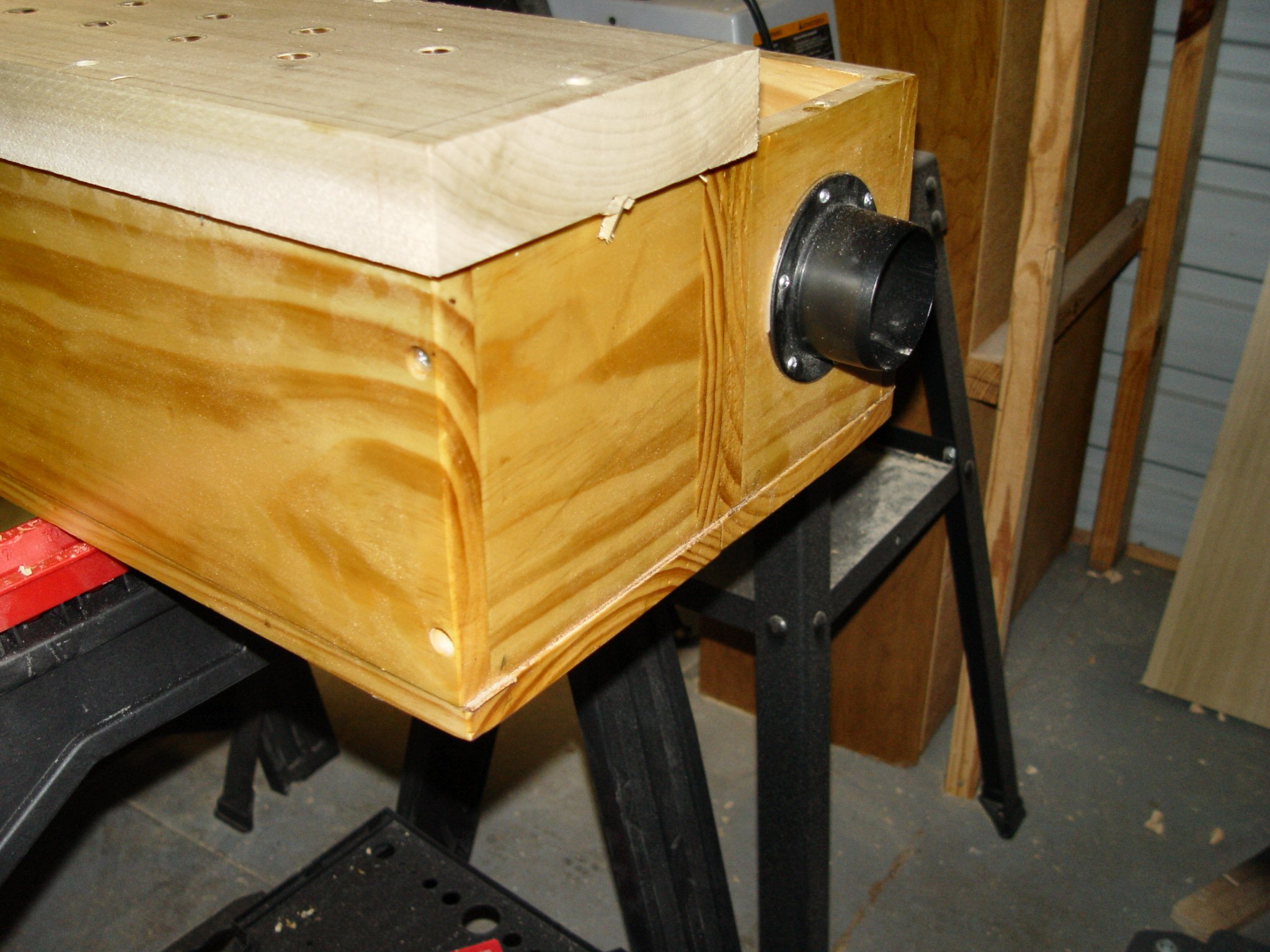
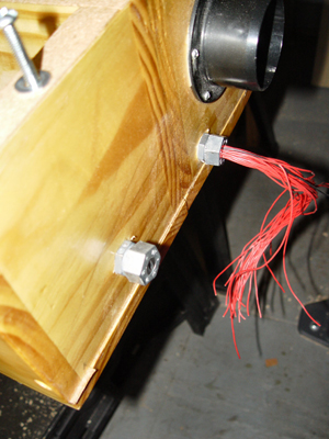
Wiring is brought to chest exterior through
air-tight compression fittings. Flange at top right is for the air supply
line. Since these chests are for church organ application, there is only
a wind connection on one side. For theatre organ use, a second flange
would be installed on the opposite side to accommodate the tremulant line.

Basic design of the toe board (shown inverted)
has Peterson magnet pallets installed over 3/8" and 1/4" drilled
ports.
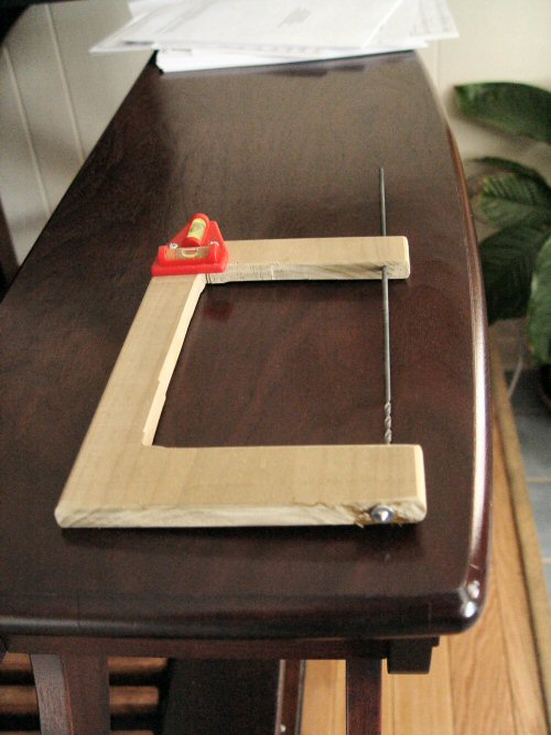
Special tool, purchased from Peterson Electro-Musical,
permits perfect fit of valve on toe board underside. The Device marks
screw hole locations and even punches indentations for drilling.
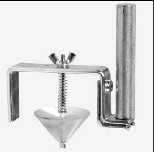

The special Peterson tool for placing electric
valves on chest. Tool marks and punches screw hole and also produces indentation
for locking tab
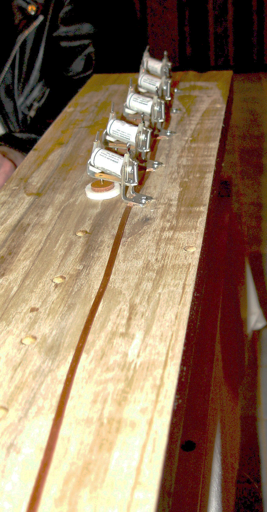
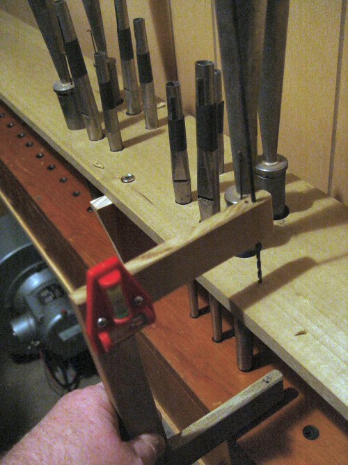
Here, the magnets are secured to the toe board
underside by means of 7/8" wood screws. Note copper braid used to
provide frame ground to magnets. Each magnet has negative side of coil
bonded to the frame.
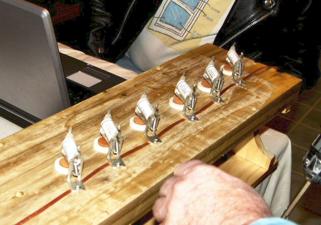

Another view of magnets being installed.
Completion of magnet placement. Next step will
be to wire the components. In these views, the toe board and rack board
are pre-drilled, test fitted to the chest box and pipe work, and varnished.
material on surface above is a light coat of talcum powder intended for
keeping the pallets from sticking to the newly varnished wood.

Close-up view of the Peterson magnet assembly
installed on the toe board underside.
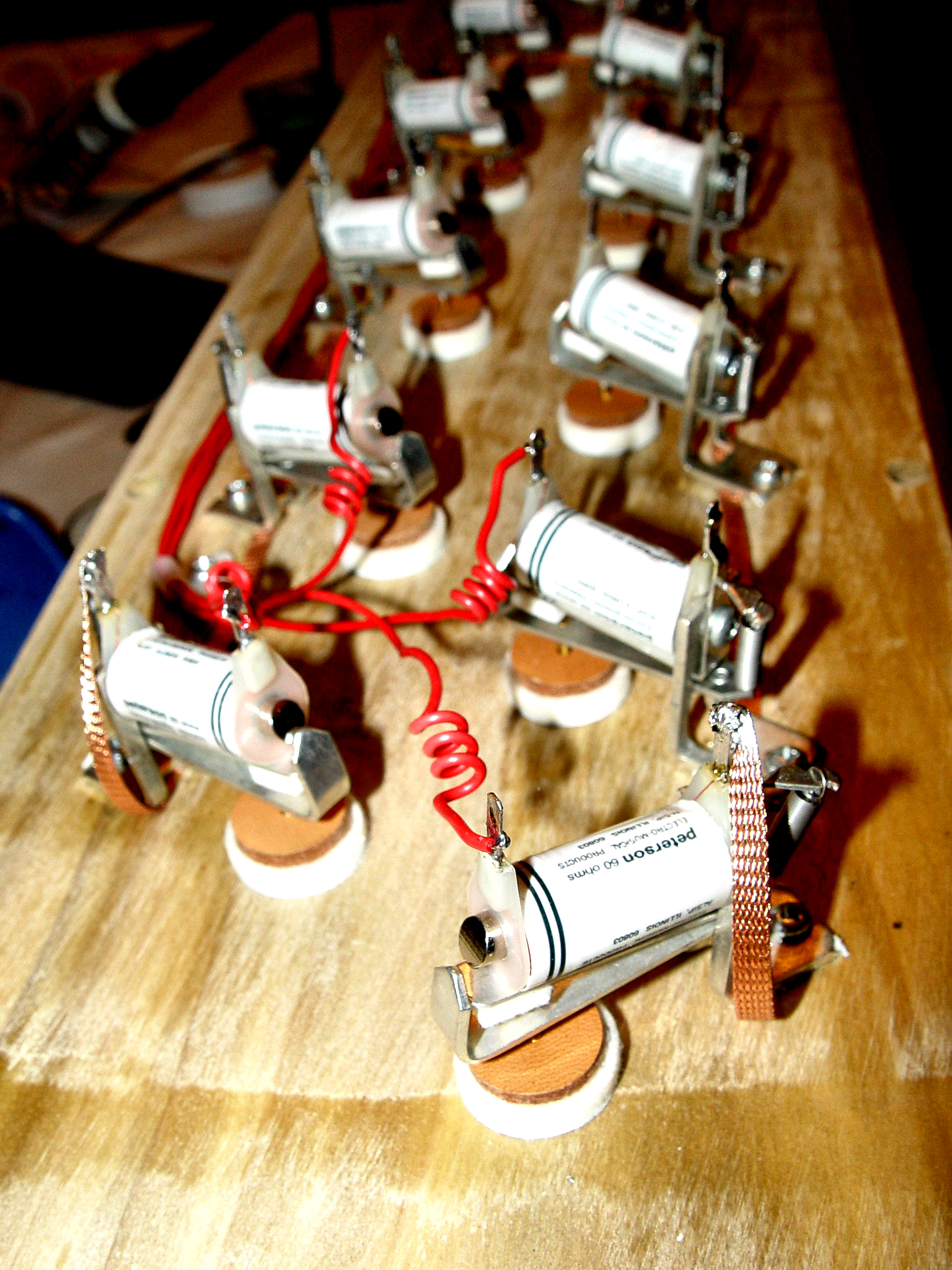
Method of wiring positive connections to chest
magnets. By coiling the wires, there is less chance of a wiring getting
broken from the turbulencee or air in the chest.
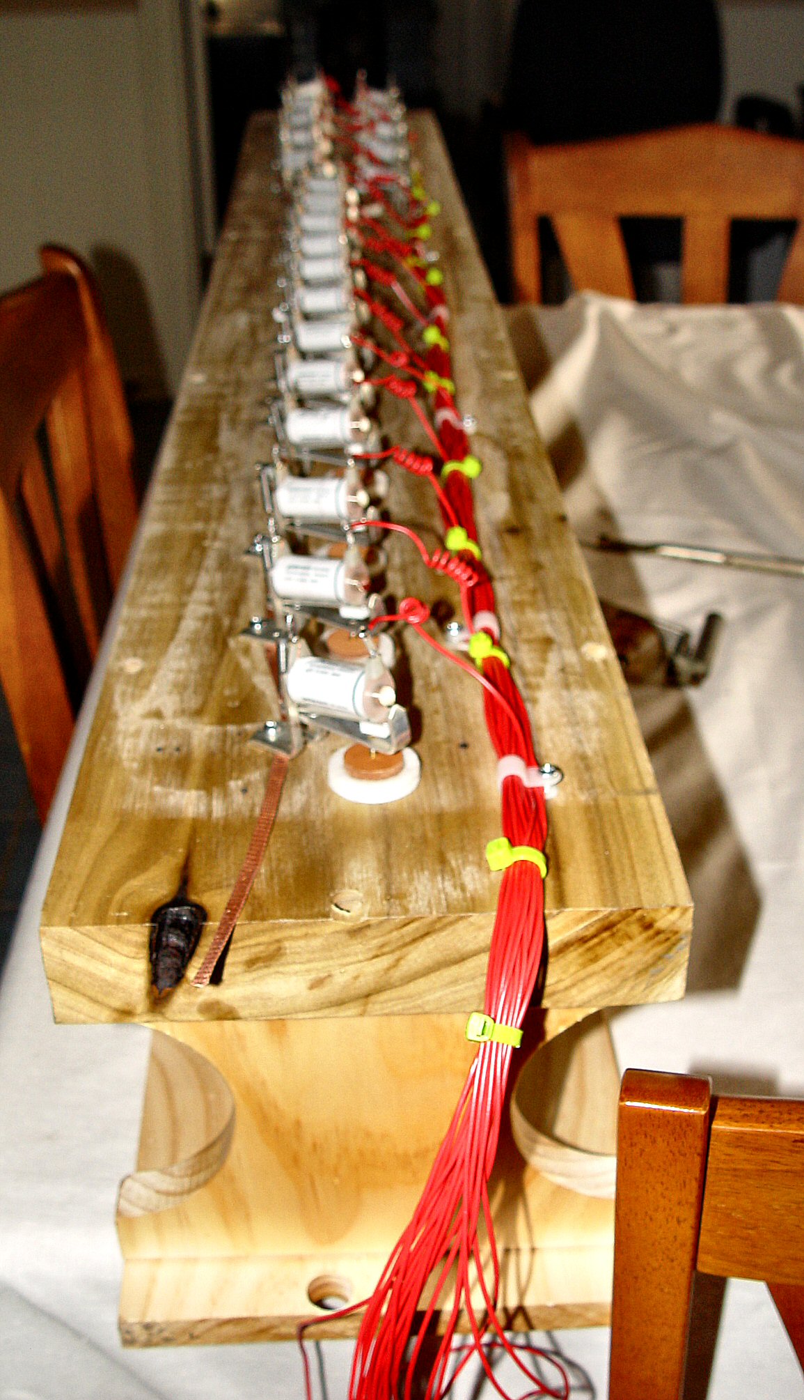
Wiring completed. Toe board is now ready for
gasket installation.
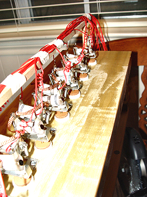
On the second chest section, the valve placement
is different, and this requires a different method of wiring. An overhead
wiring trestle was constructed to support the conductors and keep them
clear of moving valve parts.
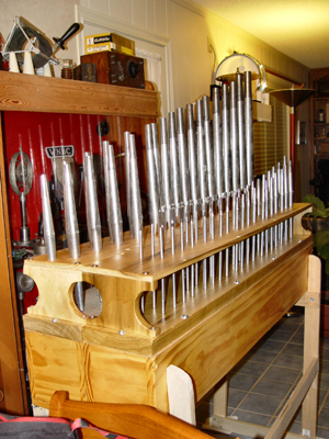
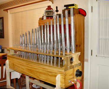
Finished view of pipe chest from two different
angles. Note specially constructed frame designed so
that chest can be dropped into frame during assembly